Control Power for Metal-Clad Switchgear
The primary control power for metal-clad switchgear comes from two sources: DC control supplied by a battery with a charger, and AC control supplied from a transformer. The control power for UL/ANSI metal-clad switchgear must have sufficient capacity to meet the maximum power demand under any operating condition. During relay operations, delivering enough power to trip the breaker is critical to protect both the breaker and the switchgear. In addition, this power source should support automatic breaker closing without direct manual operation.
Other loads on the DC control source include indicating lights, relay power, emergency lights, emergency motors, and excitation power (for brushless motors, etc.). Other loads on the AC control source include indicating lights, relay power, excitation power (for brushless motors, etc.), and equipment heaters.
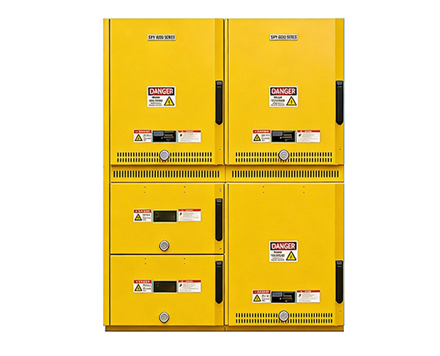
If AC control power is used, the trip power is obtained through rectified AC, which charges a capacitor inside the trip unit. Several factors determine the best alternative for each application, including system size, installation conditions, reliability, floor space, breaker operation, maintenance, and ultimately cost.
Position indicating lights are powered by a closing fuse on AC control, a dedicated tripping battery, or a tripping fuse on DC control. These lights represent a small, steady load in DC battery application calculations — each lamp is assumed to draw 0.035 A over a period not exceeding eight hours. The lights are used to monitor faults in the lockout relay, with an indicating light for each breaker, or remote indication wired in parallel with the switchgear lights. Newer control switches and lockout relays may use indicating lights integrated into the device, which must be accounted for in the load calculation.
Breaker Closing and Tripping Considerations
Automatic tripping occurs when a protective relay detects an abnormal system condition through a power-circuit instrument transformer and closes its output contact in the trip circuit. The following points must be considered when deciding between DC battery tripping and AC capacitor tripping:
- AC control may cost less than a battery system, but it is necessary to install a separate trip unit for each breaker and lockout relay.
- Although a battery system is more reliable, it requires more maintenance than a capacitor system (keep in mind that capacitor tripping also includes a small rechargeable battery system that needs periodic maintenance and replacement). For only a modest additional cost, DC closing power can be obtained through the battery tripping system. If self-powered microprocessor relays are not used, a small UPS should be included to power the AC control during emergencies or loss of power.
Basic breaker control consists of a control switch mounted on the breaker, used to close and trip the breaker. Associated with the control switch are two indicating lights — one red and one green. The red light indicates the breaker is closed and supervises the integrity of the trip coil. The green light indicates the breaker is open. This light is connected through the breaker‘s "b" contact.
For switchgear applications requiring remote control, the remote control (69CS) feature can be used. This feature provides local or remote control of the breaker under specific conditions, offering maximum operational flexibility. Breaker position switches and a breaker control switch are required to provide the permissive function. Remote closing and tripping is only possible when the breaker is in the "test/disconnected" position, while local tripping is possible when the breaker is in the "connected" or "test/disconnected" position.
When a local "trip" operation is initiated, the breaker cannot be remotely closed until the local switch handle returns to the "normal after closing" position. When the breaker is in the "test" position, closing and tripping can only be done locally. The breaker has a spring-operated mechanism consisting of a single module. The operating mechanism is equipped with a manual charging device using a stored-energy handle, and a charging device that stores energy in the spring via a motor. The mechanism includes a reclosing function. The breaker‘s front panel displays open/closed and charged/discharged indicating lights, along with a manual operating handle. The operator can charge the spring remotely, manually, or through the power source, and the breaker status can be observed on the front panel.